This post is part of a series of posts about the kinX project.
Motivation
The Kinesis Advantage comes with a built-in 2-port USB hub. That hub uses a proprietary connector to interface with a PS/2 keyboard controller, so it cannot be used with a USB keyboard controller. As the built-in hub is the natural place to connect the Logitech unified receiver dongle, not being able to use the hub is mildly annoying.
The kinX MK66F keyboard controller presently needs two USB cables: one connected to the USBFS port to supply the PCB with power and receive firmware updates (via the Teensy bootloader chip), and one connected to the USBHS port for the actual keyboard device.
Lastly, even if the original built-in USB hub had internal ports (instead of a PS/2 converter), it only supports USB 1.1, nullifying any latency improvements.
Hence, I decided to build a drop-in replacement USB 2.0 hub with 2 external USB ports and 2 internal USB ports, using the same proprietary connector as the original, so that the original keyboard USB cable could be re-used.
Design phase
Unfortunately, I could not find an open hardware USB 2.0 hub design on the internet, so I started researching various USB hub chips. I quickly discarded the idea of using USB 3 due to its much stricter requirements.
In the end, I decided to go with the Cypress HX2VL series because of their superior documentation: I found a detailed data sheet, an evaluation board, the associated schematics, design checklist/guidelines, and even the evaluation board’s bill of materials.
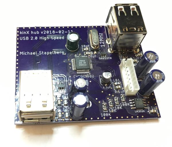
This is what the finished build of my design looks like:

Power
After completing my first build, I tested a few USB devices with my hub. The Logitech unified receiver dongle and the YubiKey worked fine. However, my external hard drive and my USB memory stick did not work. In the syslog, I would see:
kernel: usb 1-14.4.4: rejected 1 configuration due to insufficient available bus power
This is because the USB specification limits bus-powered hubs to 100mA per port. While high power usage does not come as a surprise for the external hard disk, it turns out that even my USB memory stick requires 200mA. This was a surprise, because that stick works on other, commercial bus-powered USB hubs.
A closer look reveals that all 3 commercial USB hubs I have tested claim to be self-powered (i.e. using an external power supply), even though they are not. This way, the kernel’s power limitation is circumvented, and up to 500mA can be used per port. In practice, the host port only supplies 500mA, so the user must be careful not to plug in devices which require more than 500mA in aggregate.
I changed the SELFPWR configuration pin to have my hub claim it was self-powered, too, and that made all USB devices I tested work fine.
EEPROM programming
When debugging the power issue, I originally thought the Maximum Power setting in the hub’s USB device descriptor needed to be raised. This turned out to not be correct: the Maximum Power refers to the power which the hub uses for its own circuitry, not the power it passes through to connected devices.
Nevertheless, it’s a nice touch to modify the device descriptor to put in a
custom vendor name, product name and serial number: that way, the device shows
up with a recognizable name in your syslog or
lsusb(8) output, and
udev rules can be used to apply settings based on the serial number.
To modify the device descriptor, an EEPROM (electrically erasable programmable read-only memory) needs to be added to the design, from which the HX2VL will read configuration.
The HX2VL allows field-programming of the connected EEPROM, i.e. writing to it via the USB hub chip. I found the Windows-only tool hard to set up on a modern Windows installation, so I wondered whether I could build a simpler to use tool.
Under the covers, the tool merely sends commands with the vendor-specific request code 14 via USB, specifying an index of the two-byte word to read/write. This can be replicated in a few lines of Go:
dev, _ := usb.OpenDeviceWithVIDPID(0x04b4, 0x6570)
eepromRequest := 14
wIndex := 0 // [0, 63] for 128 bytes of EEPROM
dev.Control(gousb.RequestTypeVendor|0x80,
  eepromRequest, 0, wIndex, make([]byte, 2))
The EEPROM contents are well-described in the HX2VL data sheet, so the rest is easy.
See https://github.com/kinx-project/mk66f-blaster for the tool.
Lessons learnt
-
If possible, design the PCB in such a way that components you think you don’t need (e.g. the EEPROM) can optionally be soldered on. This would have saved me a PCB design/fabrication cycle.
-
Get the evaluation board to figure out the configuration you need (e.g. self-powered vs. bus-powered).
Next up
The last post introduces the processing latency measurement firmware for the FRDM-K66F development board and draws a conclusion.
I run a blog since 2005, spreading knowledge and experience for almost 20 years! :)
If you want to support my work, you can buy me a coffee.
Thank you for your support! ❤️